Saturday 4 November 2017

DIY IoT automatic money collection in canteen settings

To be named

Project Supervisor : Teo Shin Jen

The situation

My mom works really hard at a secondary school canteen selling snack to students. I being her son want to alleviate her workload because i see first hand when I am helping her with the store how tough it is to run a small scale canteen stall. Being a computer engineer student at Singapore Polytechnic, I have worked on many IoT project and participate in a few hackathons. I want to create a IoT solution that automate money collection and display the sale data for my mom in a fairly meaningful manner. Being only able to help my mom during Saturdays (external students come in the school for after school lesson), due to my commitments to school. I have identified a few inefficiency that my mom experience when running the store. My goal is to eliminate all or most of the inefficiency for a reasonable price so that my mom has more time to do what she wants. Also, i believe all the small thing should be done by machines, so much time is waste doing nonsense.

The problems 

My mom sell snack stuff (eg. nugget, sandwich, coffee, drinks). I not so sure how she runs the store during weekdays where the actual students come, i only am able to help her with the store on Saturdays where external students uses the school facilities. The biggest problem comes when my mom comes home with the money, she has to count the total money sometimes makes me count the money which is an inconvenience. After that she is just tired and sleep for the rest of the day. Partly the reason would probably that she wakes up early for food preparation. From my observation, there is a lot of inefficiency in how she run the store. She has to count money and serve the student while more and more student rush to get their food. Regular students may know the price but new students don't know, which can slow down the process. This handling of money is very inefficient because honestly takes the most time cause you how fumble the coins for change. Basically, i trying to make the money collection more efficient saving her time. 

Why am I doing this?

The food items that my mom sells, sell for very little margins. So, it give her little reason to invest into a money counter or a cash register. Also, my mom has this dilemma where she has trouble predicting how much students are going to eat today. Sometimes, she will be able to sell everything but other times she will have tons of leftovers for my me to eat, which is't bad but very unhealthy. The IoT part of this project is to overcome this problem. Sales data can and will be useful for my mom to predict the amount of food to prepare. And also because I can.

The plan

I'm still in the very early stages of the project, I have a lot of things to sort out especially the technology part on money collection. The whole tech will probably be done on arduino (arduino very cheap) or if needed a rasppi. 
My mom being technologically-challenged not to mention the students we will need to educate on how to use my solution, I will need my solution to be fairly user-friendly.

To be updated....
Saturday 18 February 2017

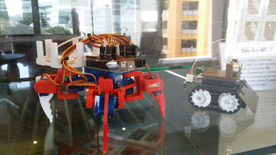
Quadruped

Project Supervisor : Teo Shin Jen


Today i will be showing you how i made my own quadruped. I was only a year one student at Singapore Polytechnic  that time when I was doing this small project. Having no prior knowledge of electronics or circuits, I met with many obstacles along the way. Hopefully after reading through my post, you would be able to learn from my mistakes and finally start your own projects. Currently as of writing this, I am already year two. I should have documented it earlier. now i try my best to recall and write it down.


Plans:

For the micro controller, I am using a Arduino Uno. For the servo moving the legs of the quadrupeds, SG90 9G Mirco Servo is used. Since this was my very first project, all the part were provide by my project supervisor. The idea for this project came from http://www.thingiverse.com/thing:343420.

1: Testing 

The first step I did was to test all the 8 servo that was given to me using the Arduino sweep example program ( https://www.arduino.cc/en/Tutorial/Sweep ), as advised by my project supervisor. Although testing a few servos might be troublesome, it is a good habit to start cultivating early on especially when you start to move on to more complicated projects. 

2: Circuit Design

I had a lot of trouble when it came to this step. The first new concept that i couldn't understand that well was the doing the Arduino shield. Shields are boards that can be plugged on top of the Ardunino PCB extending its capabilities. To a veteran in electronics, this concept will be very simple but to someone who has never done anything like this before is very daunting. Other problem would that i didn't quite understand quite how electricity worked, my very first few shield I made had the pins in wrong position and the ground wrongly wired. Eventually, I managed to produce something that was workable.

3: Fabrication


For this step, I made a little error at the start. I downloaded the files from the project linked above and printed it out using my school’s 3D printers. I assumed that all of it will fit together nicely, however this is not always the case. I tried to re scale the 3D object to hopefully be able to fit all of it together. It did not work out. So, i had to learn how to draw out my 3D projects. The software i used was SketchUp. At that point of time, I had a very helpful Technical Support Officer (TSO) to teach me about the basic of using Sketchup. To convert skp file to stl file, go to the Window tab in SketchUp. In the tab, click extension warehouse. Search for an extension called SketchUp STL and install. This will allow you to export the SketchUp object in stl. Links to download my version of quadruped will be down below.


4: Assembly

Now is the time to put everything together. For the servo to slide into place, i had to disassemble each of them and put them in place. To disassemble the servo, remove the screws at the bottom holding the servo together. Then carefully remove the cover remember how each of the gear was position. Sometimes when the print job was bad, you will have to sand the edges to get the servo in place. After sliding the servo in place, assemble the servo as you disassembled. To secure the shoulder, I used 4 0.5 cm nuts. Each of the servo is secure by 0.5 cm screws that i brought from a screw shop. The hip and backbone is secured by a 1.5 cm deep screw while the rest is 0.5 cm deep screws. The body and the backbone is secured with a washer and a 1.5 cm deep screw.

5: Code

Depending on the circuit design, the servo will be attached to different pins. During my testing, I use the arduino sweep example to test the range of movement for the quadruped.


Wok in Progress....


Part link: http://www.thingiverse.com/thing:2130743

Code link: https://gist.github.com/ljunqian/6d3f5a4ec7d4fab077c56568e96ebe0d